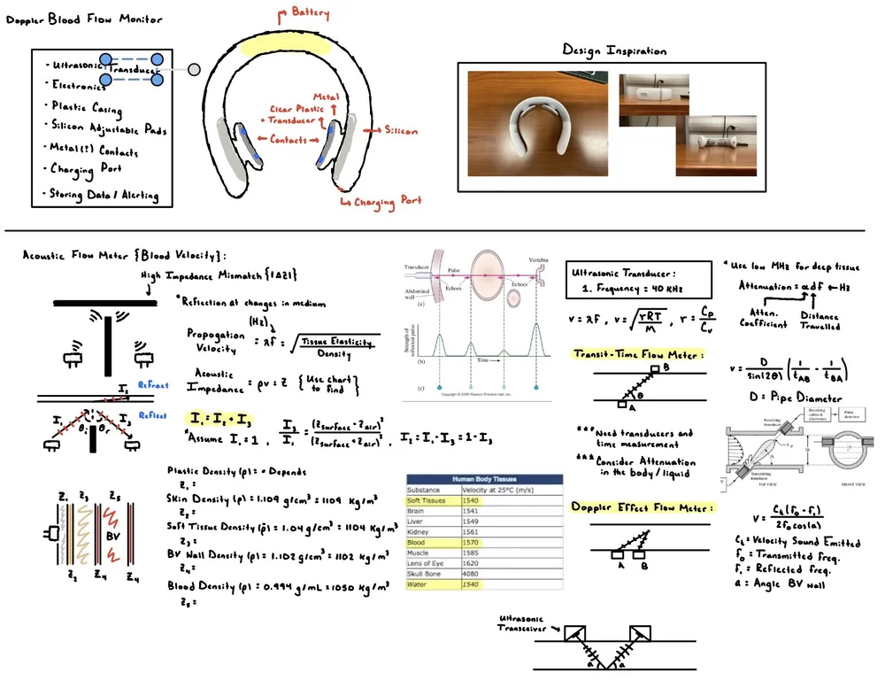
Carotid Artery Cardiac Output Monitor
I developed the electrical and mechanical systems for a wearable continuous cardiac output monitor, combining Doppler ultrasound and arterial applanation tonometry on a single neck-worn device, with FEA-validated pressure estimation under 5% error.
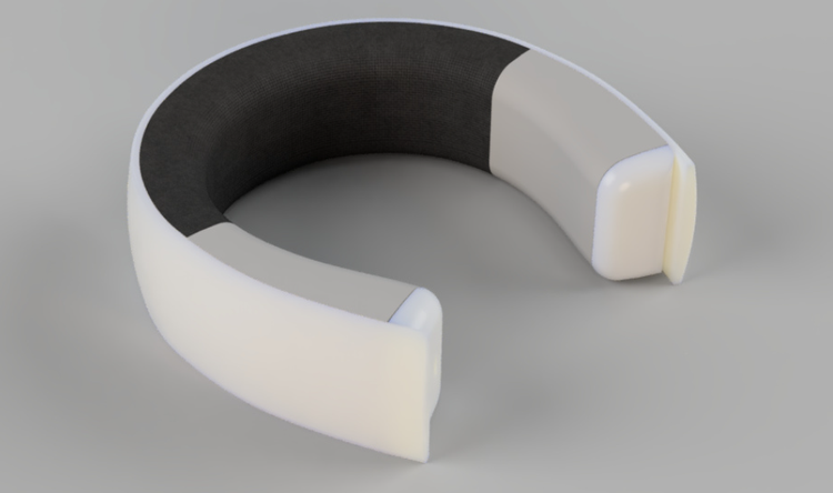
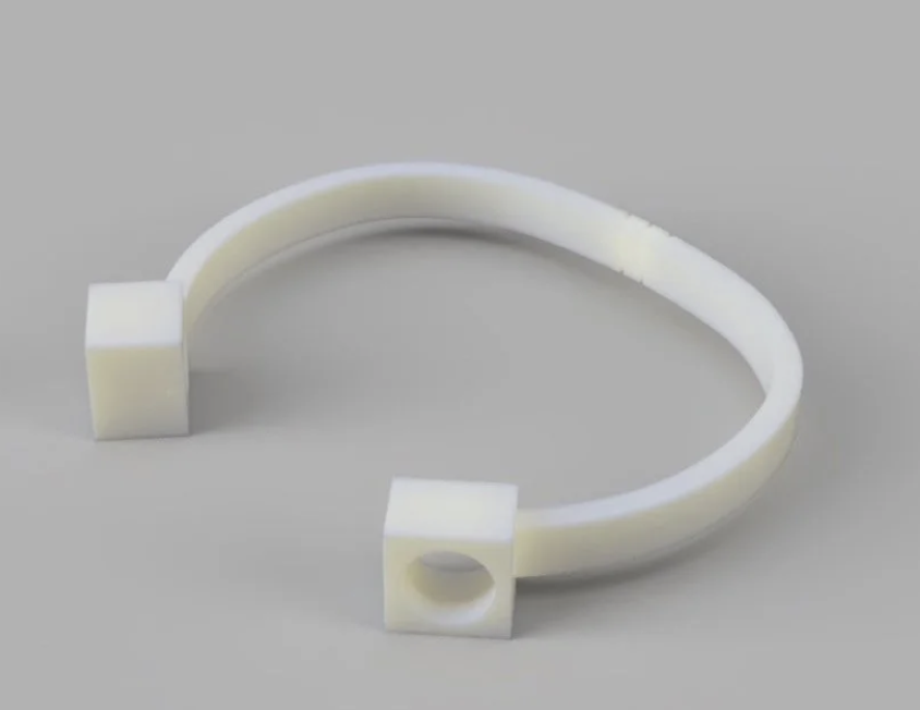
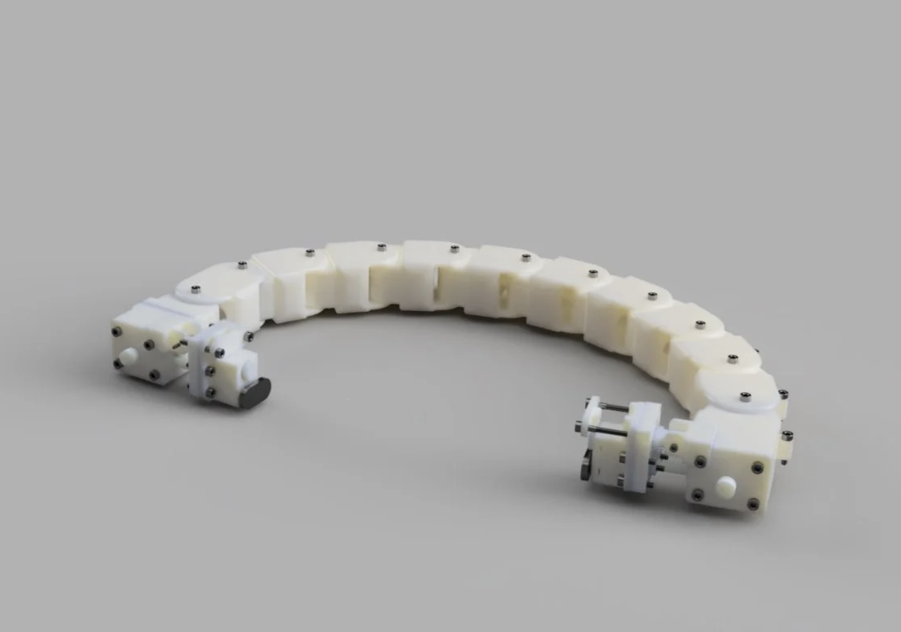 V3.0 Full Design Rendering
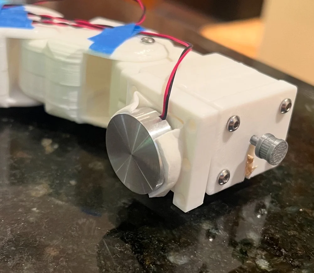
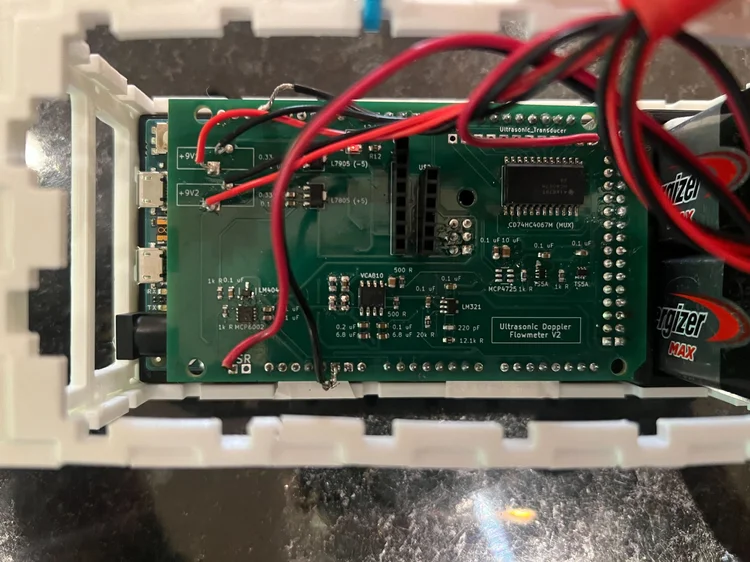
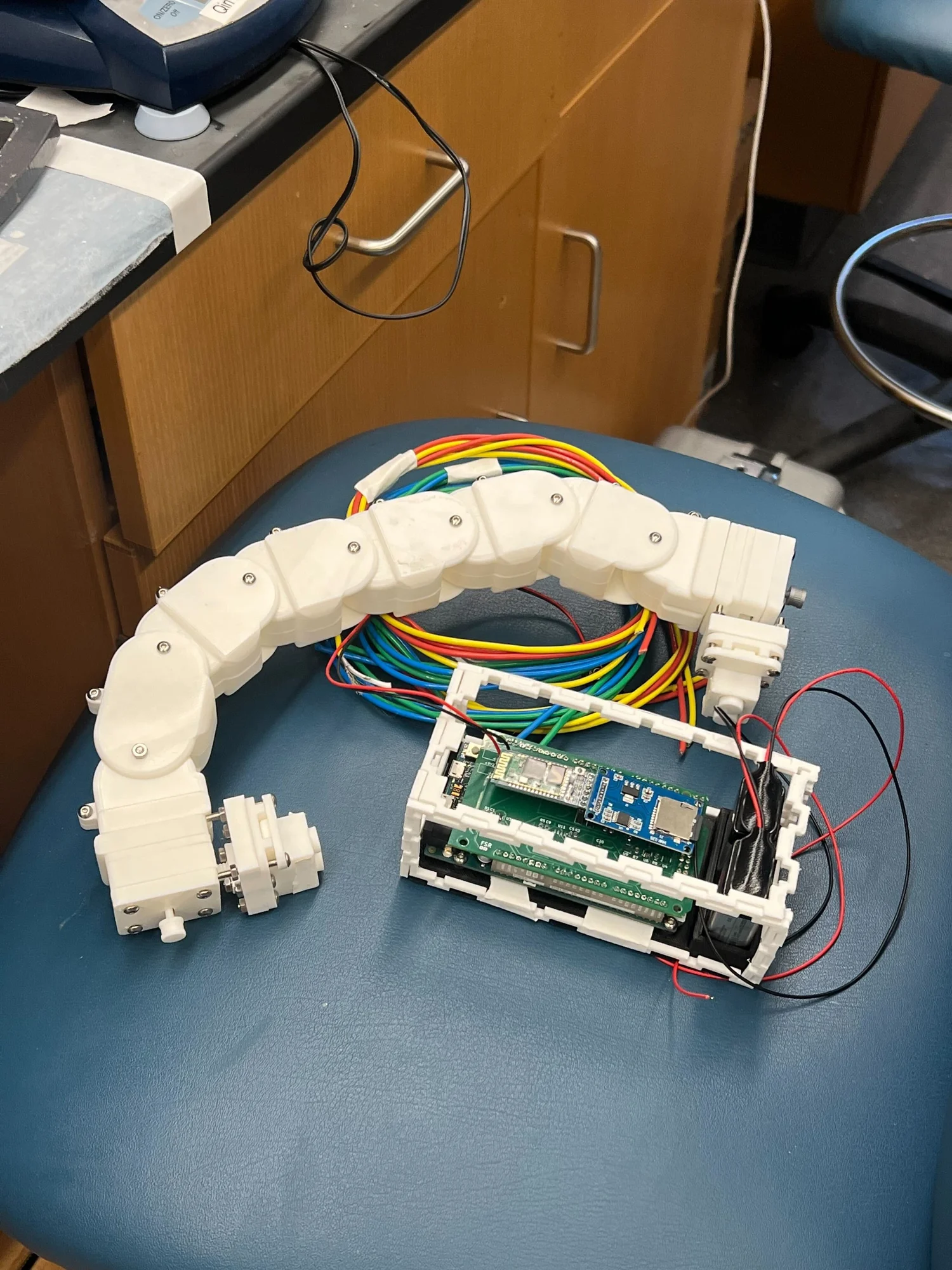 Final prototype, Alpha V3.0
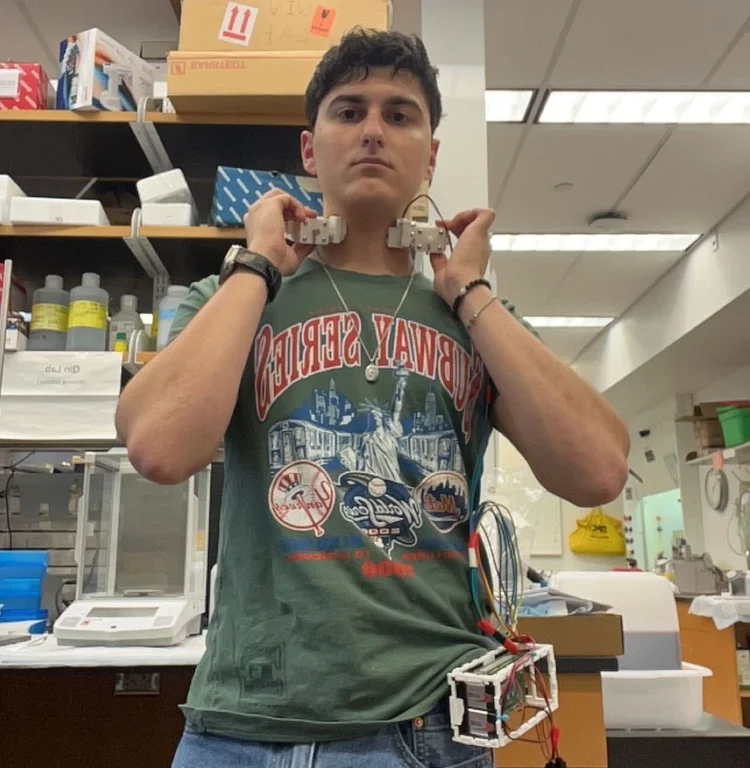 Worn over the carotid artery
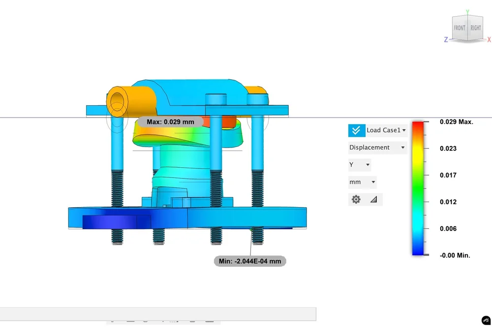 ANSYS: applanation deformation study
 Dr. Yi-Xian Qin's lab, Stony Brook University
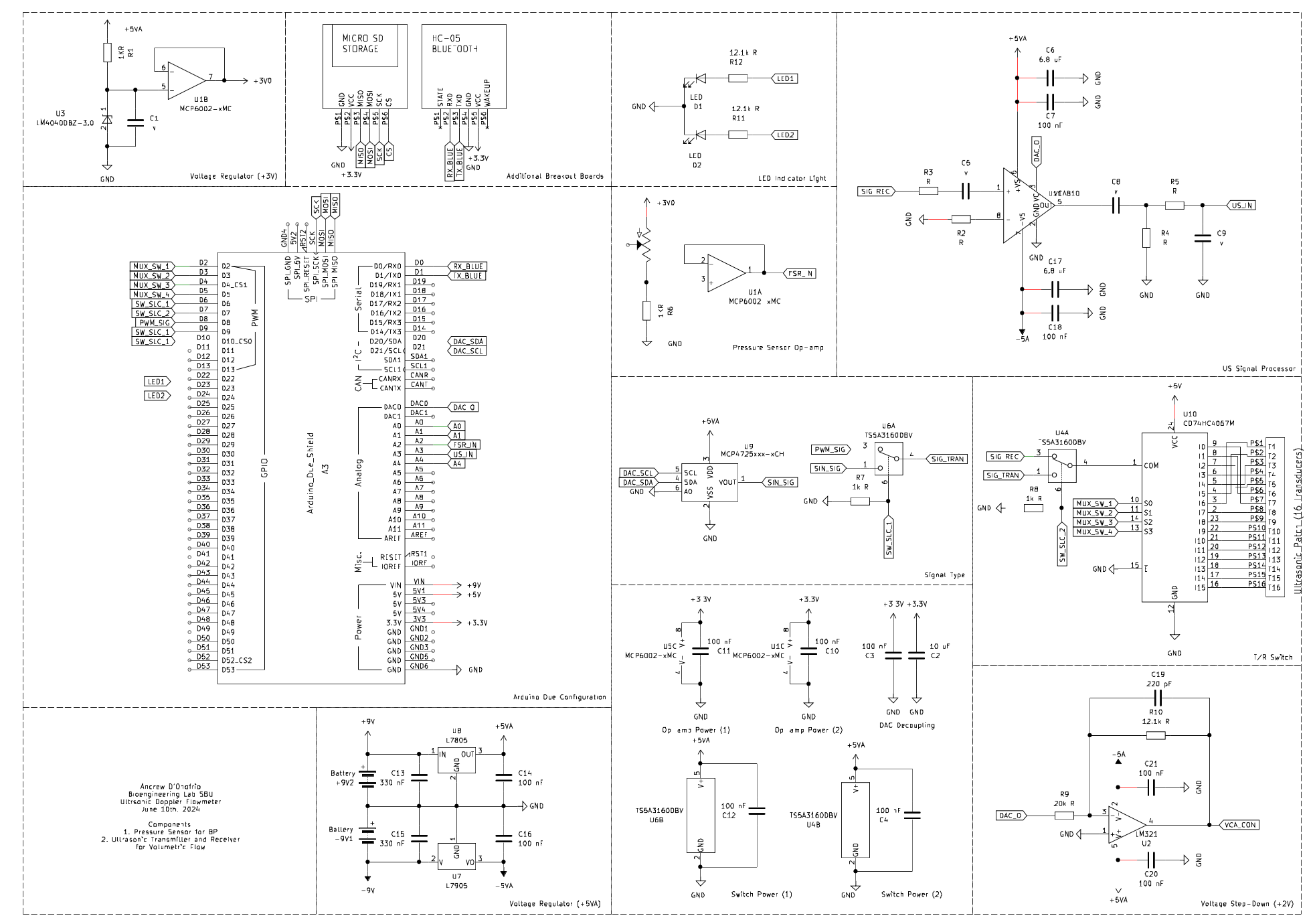
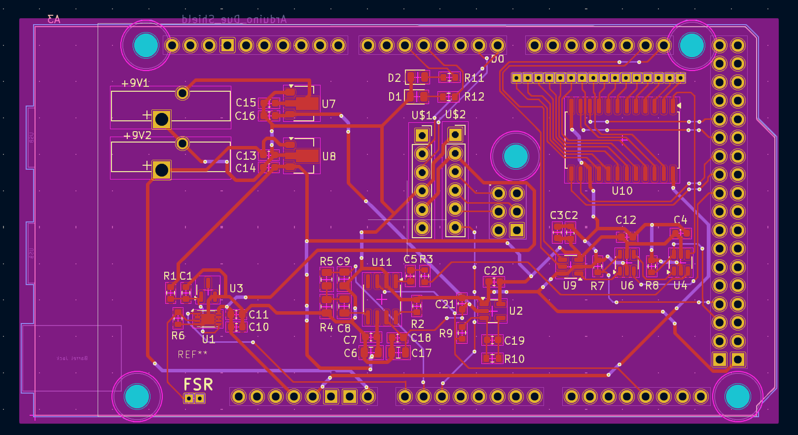
PCB Design (KiCAD)
Doppler Ultrasound
Applanation Tonometry
ANSYS Static Studies
Fusion360
Arduino / Embedded C
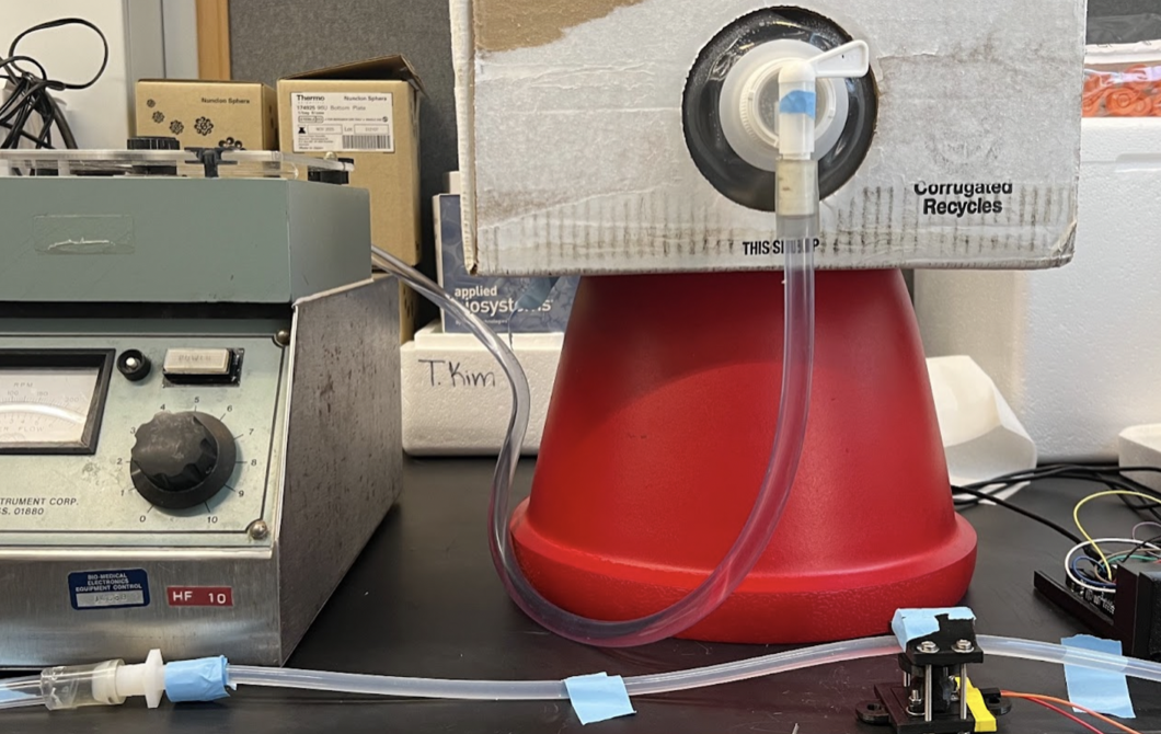
Rapid Prototyping
Verification Testing
Technical Leadership