Wing Blade Weight Optimization via FEA
MAE 4700 · Cornell University · 2-person Team (Member)
I led the problem framing, mathematical modeling, mesh refinement strategy, and design comparison computations for an FEA-based parametric optimization of a NACA 0012 wing blade in ANSYS, achieving a 41.8% weight reduction while satisfying all stress and deflection constraints.
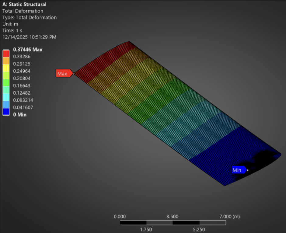 ANSYS deformation and Von Mises stress for the optimized design
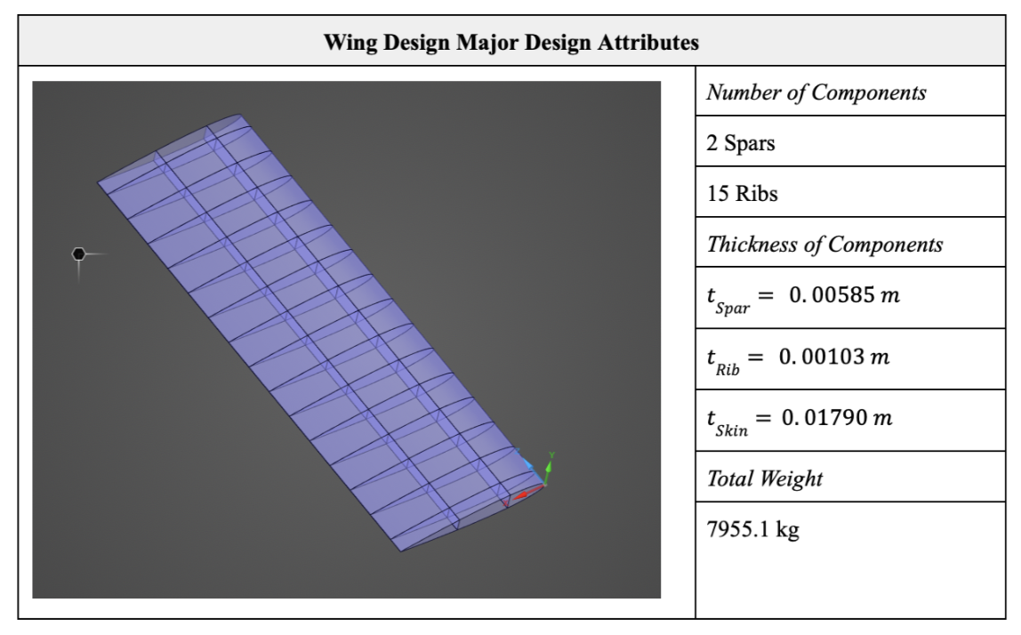 Final design: 15 ribs, 2 spars (Design 4D)
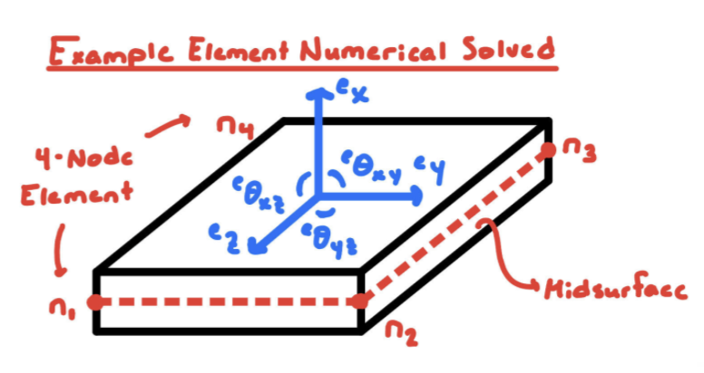
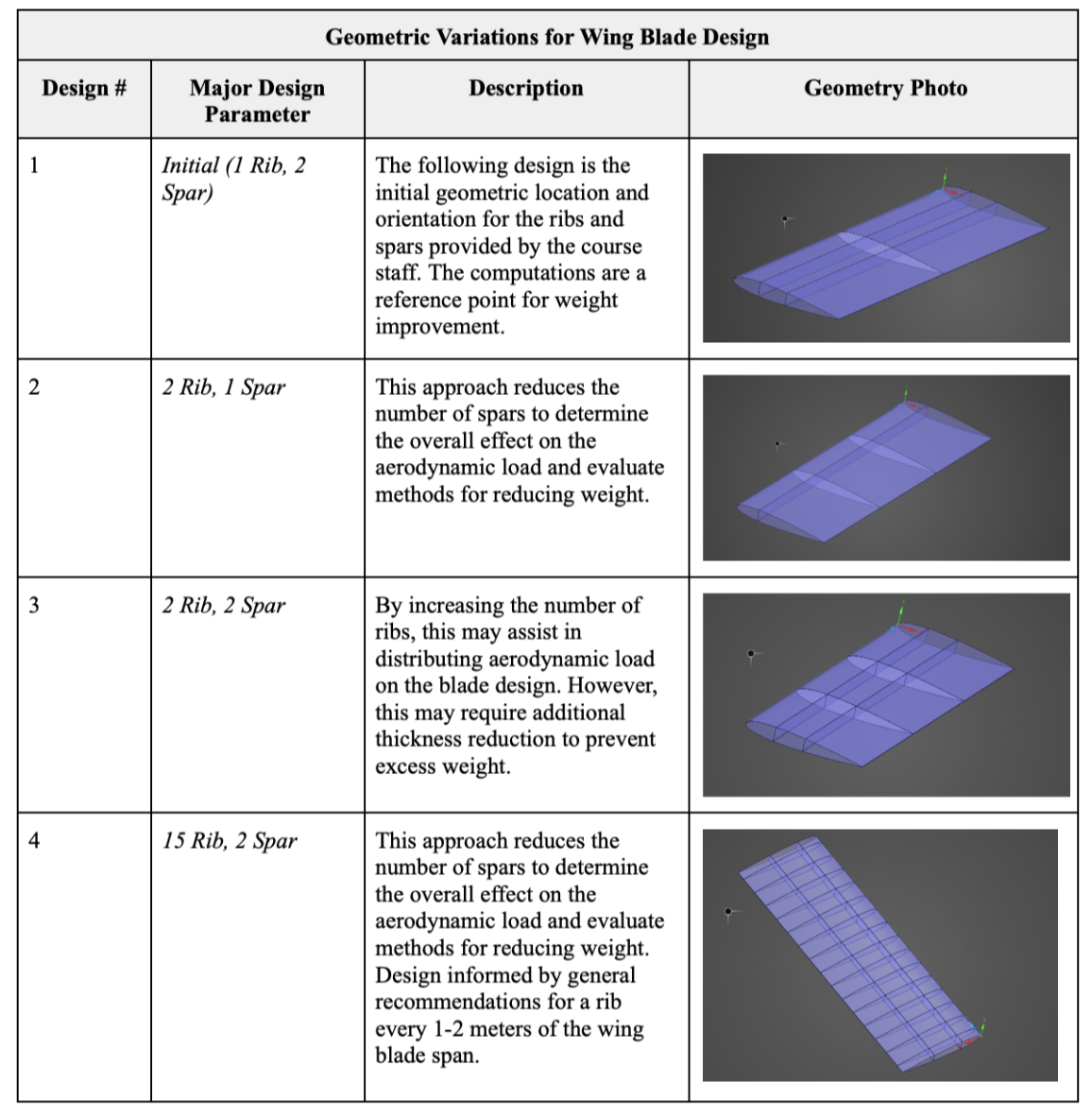
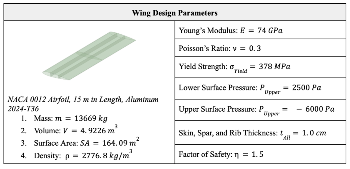 Blade geometry and parametric design variables
ANSYS Mechanical
Finite Element Analysis
Thin Shell Theory
Parametric Optimization
Structural Analysis
Mesh Refinement
Von Mises Stress
Weight Reduction